
Working Drawing
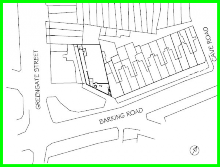
Block Plans
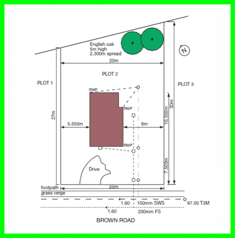
Site Plans
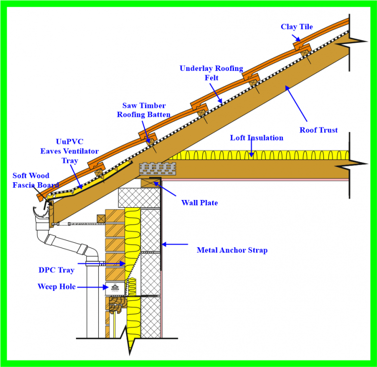
Assembly Drawings
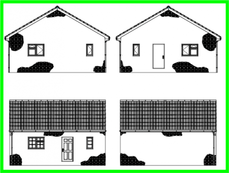
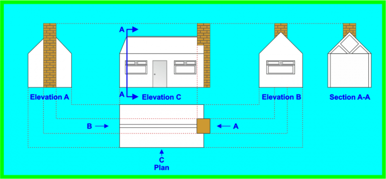
Elevations Drawings
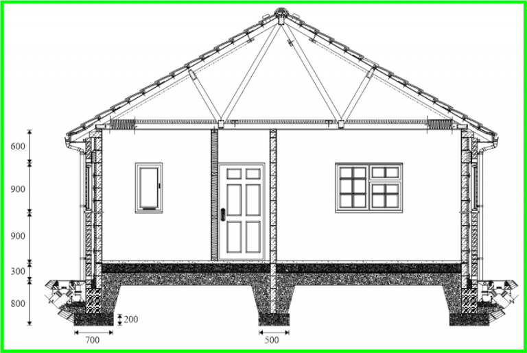
Sectional Drawings

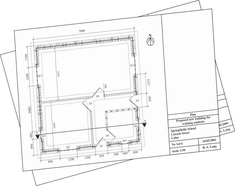
Section line AA
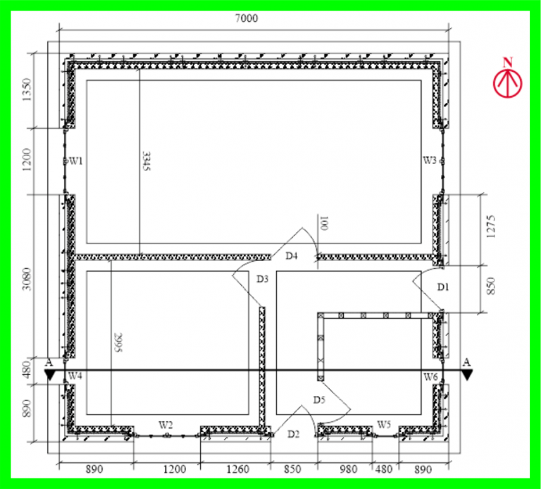
Floor Plan
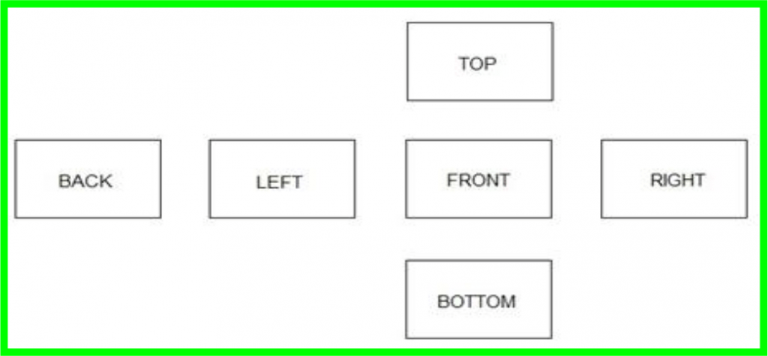
First Angle Projection
Orthographic Projection
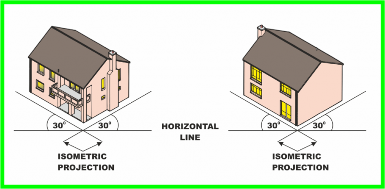
Isometric Projection
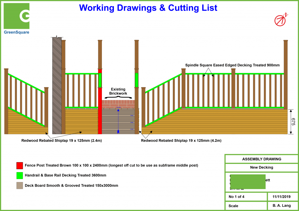
Drawing 1 of 4
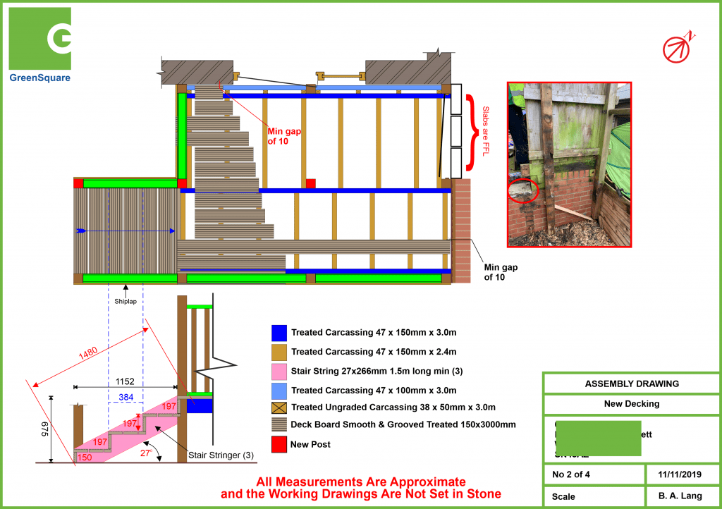
Drawing 2 of 4
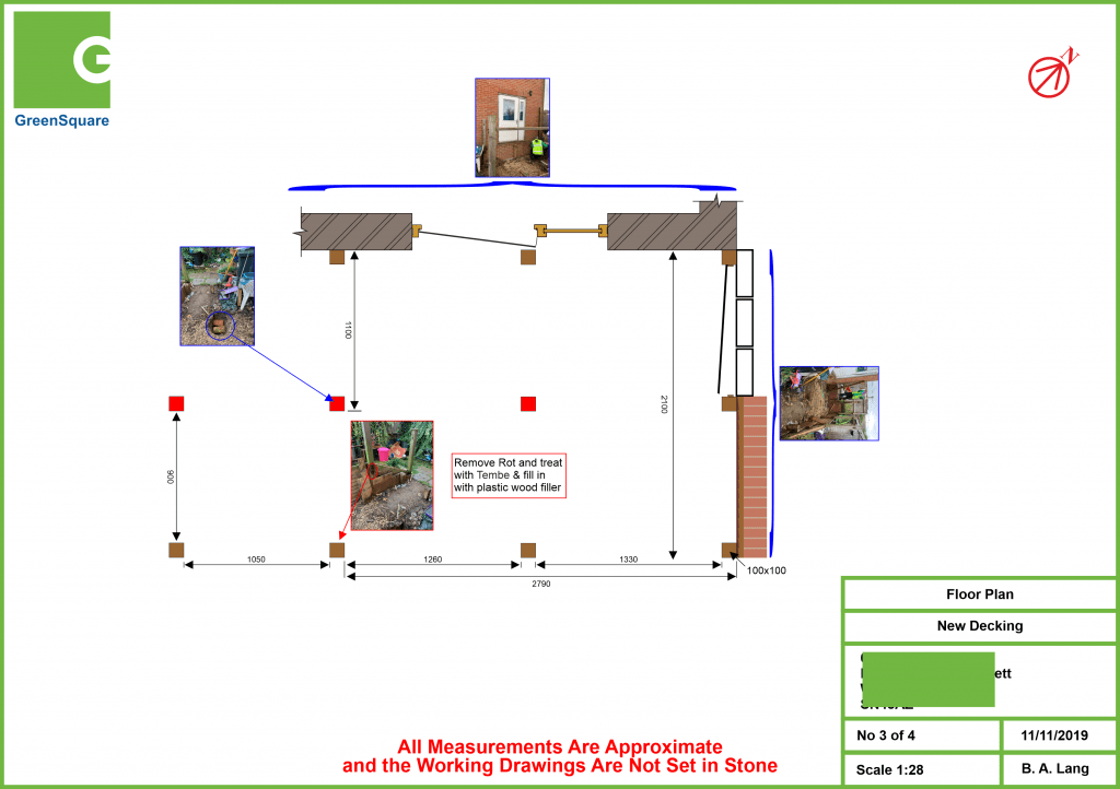
Drawing 3 of 4
Drawing 4 of 4