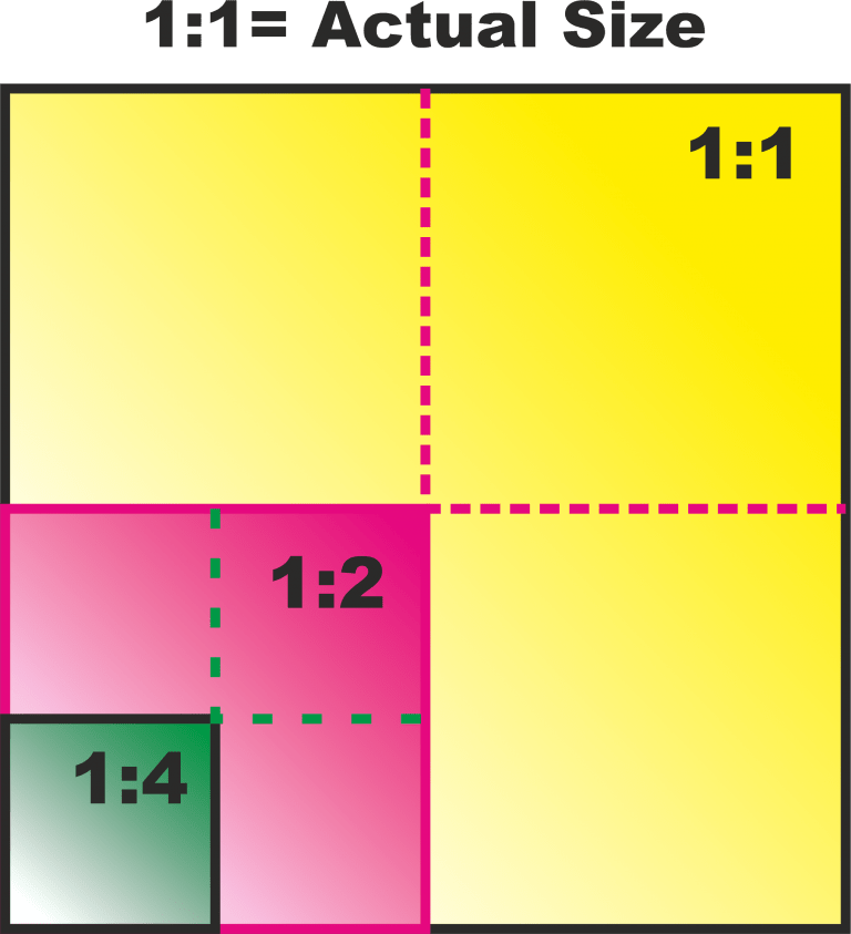
Scale Ratio
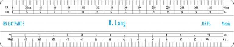
Scale Rules
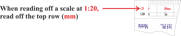
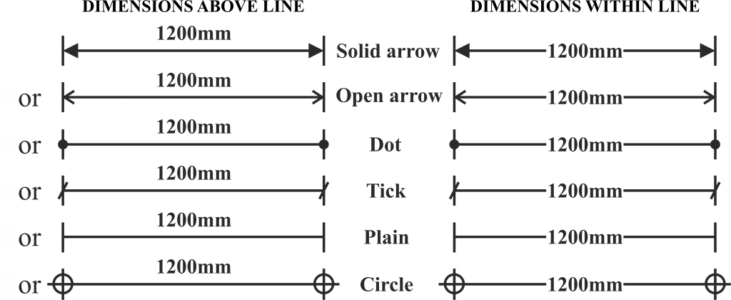
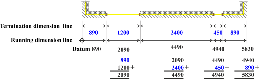
Reading off Scale


Thin Line construction and dimension lines

Thin Chain Line Centre lines

Thick Line Main outlines

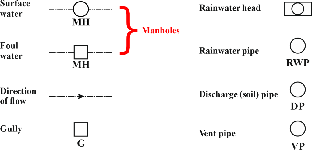
Thick Chain Line Pipe lines, drains and services

Section Line Showing the position of a cut (the pointers indicate the direction of view)

Medium Line General details and outlines

Broken line Showing details which are not visible

Breakline Breaks in the continuity of a drawing
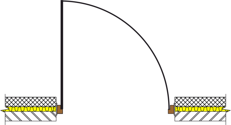
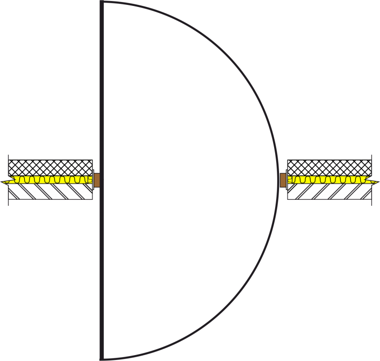
Single door (single swing)
Single door (double swing)
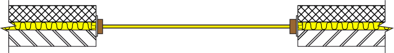
Window
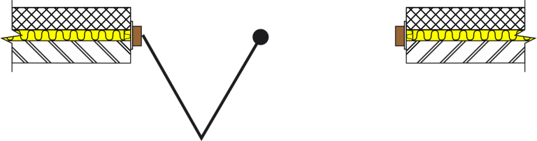
Side Hung
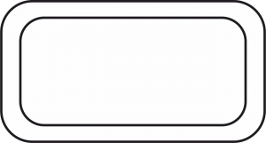
Bath

WC (Water Closet)

Sink
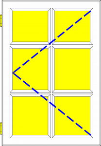
Window Side Hung
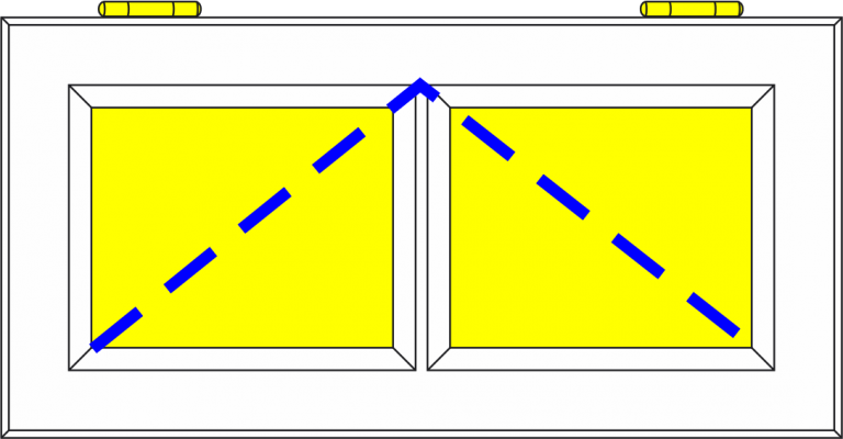
Window Top Hung
Window Side Hung
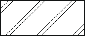
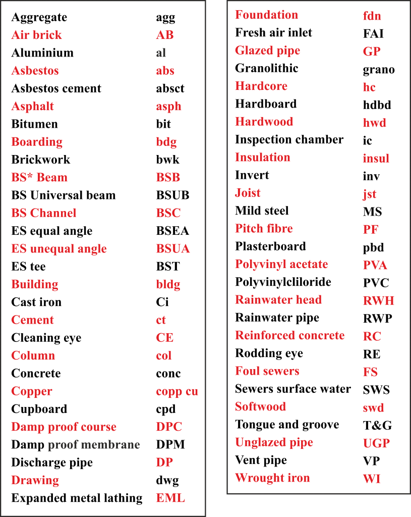
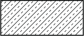
Brickwork
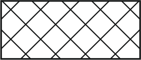
Blockwork
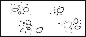
Concrete
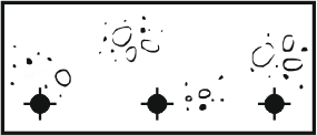
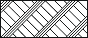
Reinforced Concrete
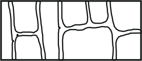
Stonework
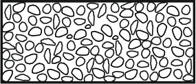
Rubble
Hardcore
Soil
Granular fill
Rubble

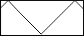
Insulation

Plaster-render

Damp Proof Course

Glass

Metal

Steel and Metal Work